The shape of the Wankel rotor
I’ve written a number of posts about curvilinear triangles that are not the Reuleaux triangle, including MIT’s Kresge Auditorium, triforce string art, valve covers, a patio table, and the logo of Whale Cove, Nunavut. I’ve long intended to write about another obvious topic in this theme, the curved-triangle rotor of the Wankel engine, but was finally pushed into doing so by seeing that two recent popular mathematics books, How Round Is Your Circle? (2008) and Icons of Mathematics (2011) repeat the falsehood that Wankel rotors are Reuleaux triangles. They are not.
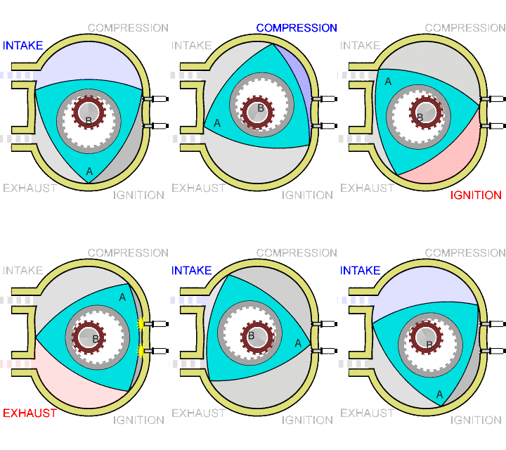
Wikipedia has a good visualization of how Wankel engines work, which I’ve copied below. They go through the same four steps as a conventional four-stroke combustion engine, in which a piston pulls away from the combustion chamber, sucking in a mixture of fuel and air, pushes back towards the chamber, compressing the mixture, ignites the mixture, pushing the piston back out and applying force to the drive shaft, and then pushes back towards the chamber, pushing the exhaust out. The difference is that in a Wankel engine, these four steps happen at four different locations within the combustion chamber, as the gases within it are pushed around by a curved triangular piston, the rotor of the engine.

The driveshaft in the engine is the fixed smaller gear in the center of the animation; in the actual engine, this gearwheel would itself be spinning, but this is not shown. The triangular rotor connects to the driveshaft by an eccentric planetary gear, and spins around the driveshaft like a hula hoop around a spinning dancer. The gears have teeth and radii in the ratio 3:2, causing the driveshaft to spin three times faster than the rotor. As it does so, the three corners of the rotor (the “apex seals”) stay in contact with the outer wall of the engine, called its stator, so that the gases in the engine do not leak between different phases.
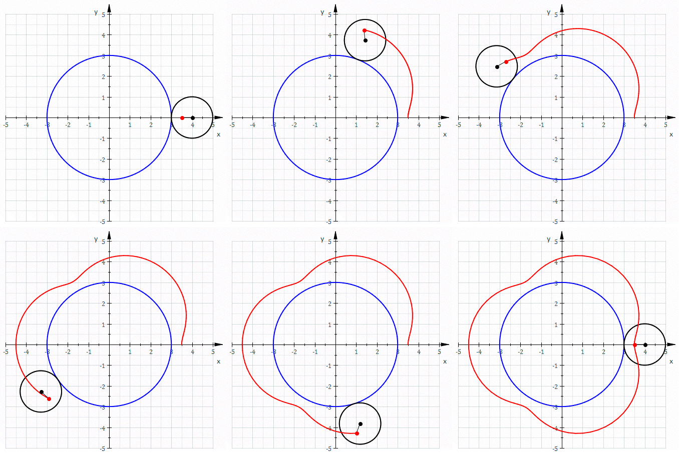
The shape of the stator is not determined by the curve of the rotor itself, but only by the trajectory of the moving apex seals. This trajectory is a curve called an epitrochoid. If you’ve ever played with a spirograph, you know what an epitroichoid is: it’s what you get by fixing one circular disk, letting another circular disk rotate around it, placing a point somewhere within the rotating disk, and tracing the curve that it follows. Here’s another Wikipedia animation:

Different ratios of radii between the inner and outer disk give you different numbers of lobes in the curve, and different placements of the moving point in the outer disk (closer to or farther from the disk center) give you curves that are closer to a circle or more curvy. Placing the moving point on the outer circle itself gives you pointy rather than curvy epitrochoids, and placing it even farther out turns the inner bulges of these curves into self-crossing loops.
Spirograph trajectories differ from rotating apex seal trajectories in at least three ways: in the Wankel engine, the central circle (the driveshaft) rotates rather than being held stationary, the outer circle (the planetary gear) surrounds the central circle rather than being outside it, and the point whose motion is being traced (the apex seal) is outside the outer circle rather than inside it. Nevertheless, the shape is still a two-lobed epitrochoid; see the “double generation theorem” of the Bernoullis, as described by Nash,1 for why the same curve can be generated in multiple ways. Modulo the scale of the whole system, there is one free parameter controlling the precise shape of this epitrochoid: the ratio of the distances from the center of the rotor to the apex seals and to the planetary gear. If the apex seals are too close in, the planetary gear will bash into into the stator; if they are too far out, the stator will be close to circular and there will be little change in pressure from one part of the combustion cycle to another, losing engine efficiency. The choice made in actual engines is not the one that places the apex seals as close as possible, but seems to involve more careful optimization that considers the shape and size of the regions formed by the rotor and stator at different stages of the combustion cycle.
Once the stator shape has been determined, one can then proceed to answer the question we started with: what is the shape of the rotor? The main design constraint is that it should touch or at least stay close to the inner bulge of the stator (on its “side seals”), to prevent exhaust gas from flowing back around to the intake. The shape that achieves this can be understood by a thought experiment in which we imagine the rotor as somehow being fixed in space while the vehicle containing it rotates around it, rather than vice versa. As the vehicle rotates, its stator passes through parts of the space that cannot be occupied by the rotor. The parts of space that remain untouched by the rotating stator are available to be used by the rotor, and should be used by it if we want a rotor that stays in contact with the stator on its side seals. Mathematically, this is described as an “envelope” of the positions of the rotating stator with respect to the fixed rotor. This envelope is a curved triangle, but not a Reuleaux triangle. Its curves are flatter than a Reuleaux triangle’s arcs, but also they are not circular arcs. As an envelope of algebraic curves, they are presumably algebraic themselves, but of higher order; trigonometric formulas are given by Shung and Pennock.2
In practice, the rotor shape varies from its ideal envelope-of-epitrochoid form, in a couple of different ways. First, as Drogosz explains,3 for ease of manufacturing it is often approximated by circular arcs rather than exactly following the envelope shape. As long as the approximation stays within the envelope, the rotor will avoid colliding with the stator, and the side seal contact is not so important near the corners of the triangle, so that’s where the approximation is most noticeable. Second, real Wankel rotors often have scoops taken out from the middles of their sides, to form mini-combustion chambers that guide and shape the combustion gases within the engine.
For more details of all this, see:
-
Nash, David H. (1977), “Rotary engine geometry”, Mathematics Magazine 2: 87–89, doi:10.1080/0025570X.1977.11976621, JSTOR:2689731 ↩
-
Shung, J. B. & Pennock, G. R. (1994), “Geometry for trochoidal-type machines with conjugate envelopes”, Mechanism and Machine Theory 29 (1): 25–42, doi:10.1016/0094-114X(94)90017-5 ↩
-
Drogosz, P. (2010), “Geometry of the Wankel rotary engine”, Journal of KONES 17 (3): 69–74, http://yadda.icm.edu.pl/yadda/element/bwmeta1.element.baztech-article-BUJ5-0031-0018 ↩